This is Kinovea 0.9.3.
This version builds upon the previous improvements in the capture side of things and brings more usability tweaks for annotating videos.
-------------------------------
Edit: this topic was originally created for version 0.9.2 but now links to version 0.9.3 of the installer and archive, fixing a few important issues that were found with 0.9.2. The description below lists the changes compared to version 0.9.1.
------------------------------
Many thanks to everyone reporting bugs and helping with the testing!
As always this post highlights the main updates, please check the changelog for a more exhaustive list.
1. Capture metadata and camera rotation
When capturing a camera Kinovea will now save a .KVA file alongside the recorded video. This file will be used by the player to read metadata that can't be saved in the file. In particular, timing information will be automatically "corrected" for high speed cameras, and the time origin (time "0") will be set to be the recording trigger event.
The camera screen now supports image rotation and this information will also be added to the captured videos. If you need to set your camera sideways or upside down this is now a fully supported scenario.
2. New capture mode: Retroactive
Up until now when capturing video from a camera, the frames were added to the output file on the fly, continuously, until recording was stopped. With the "Camera" recording mode the frames go straight from the camera to the file, in real time. With the "Delayed" recording mode the frames are taken from the delay buffer at the current delay.
The new recording mode leverages the delay buffer differently: it waits until the recording duration is reached and then copies all the frames from memory to the file in a single operation.
This approach is only workable if your final video fits entirely in memory. If you can work within this constraint this mode will be much more efficient and should allow you to take advantage of your camera's most hardcore settings.
To use this feature you can do the following:
In Options > Preferences > Recording > Recording mode and delay, check "Retroactive".
With this mode it is no longer necessary to use the "Record uncompressed video" option if you prefer not to.
Adjust the allocated memory to allow for the duration of your target video to fit entirely in memory.
Use the capture screen normally: start and stop recording manually or via audio trigger and automated max duration.
At the end of the recording period the camera will be paused for a bit while the program is actually exporting the video.
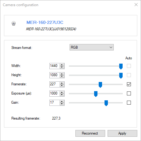
3. New Camera type: Daheng Imaging
Kinovea now supports a third type of machine vision cameras with the introduction of a module supporting Dahing Imaging cameras.
You can learn more about these cameras and check their specs at https://www.get-cameras.com/
Many thanks to get-cameras for providing a camera and technical support!
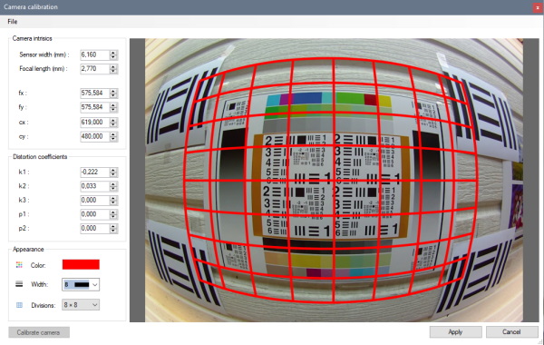
4. Lens distortion calibration
For videos that were recorded by cameras with a lot of lens distortion like GoPros, you can go to menu Tools > Camera calibration.
This dialog has been reworked to be interactive. Film a flat grid like a chessboard and play with the variables, especially distortion coefficients k1 and k2, to adjust the grid so that it matches the image.
This is obviously only an approximated fit but the idea is to make it much easier for anyone using these cameras to get decent measurements compared to not calibrating at all.
5. Linear coordinate system
The line-based coordinate system is now responding in real time to changes in the line used to calibrate it. This also means we can use this to define a rotated coordinate system without resorting to the quadrilateral calibration.
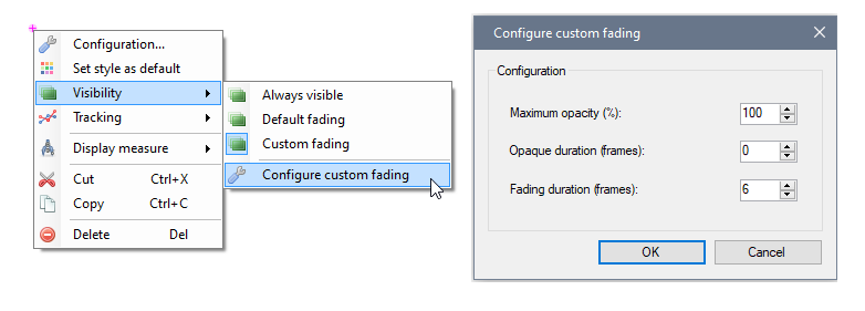
6. Drawings visibility
The option to control each drawing’s visibility independently from the others has been restored and enhanced. It’s now possible to setup the drawing so that it stays fully visible for a while before fading out.
Thanks!
Don't hesitate to post feedback, questions, feature requests and bug reports! You can do this either in this thread or create new dedicated threads.