This is the documentation draft for the page "Lens calibration" of the manual.
The first post contains the documentation that will be synchronized with the manual and you can post comments to add feedback or discuss points that are unclear.
-----------------------
Introduction
Lens calibration is the process of calculating the internal parameters of the camera used to film the video. These include the field of view and distortion of the lens.
Lens calibration is currently used in two aspects of Kinovea:
- For measurements and display, the distortion is taken into account and coordinates are rectified before they are passed to the spatial calibration.
- In the Calibration validation dialog, to calculate the camera distance and measure the error of points that are outside the plane of motion. See Calibration validation.
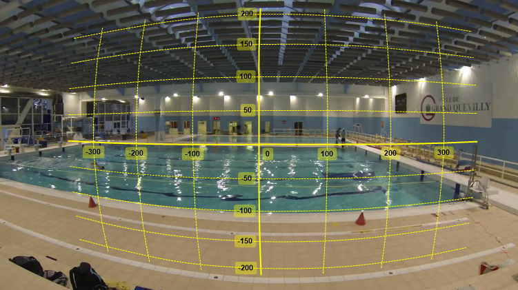
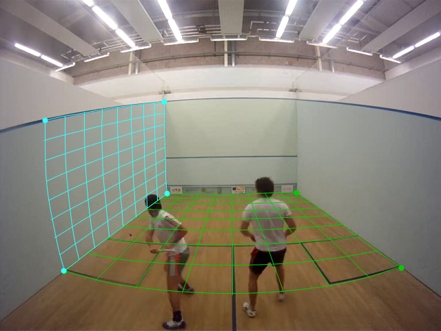
Barrel distortion exposed by a GoPro action camera and the default coordinate system after lens distortion calibration.
Lens calibration is compatible with both line calibration and plane calibration. The coordinate system, lines and grid objects are drawn distorted to follow the distortion. The images themselves are not rectified.
Lens calibration procedure overview
Here is an overview of the lens calibration procedure
- Film a calibration pattern with the camera to be calibrated
- Open the calibration video in Kinovea
- Open the dedicated lens calibration mode
- Run the automated lens calibration
- Save the resulting data to a file
- When analyzing videos filmed with the same cameras, load the saved lens calibration profile
Calibration pattern
You can find a pattern here: https://github.com/opencv/opencv/blob/m … g?raw=true
Note:
The linked pattern image states that it is a 9x6 pattern because it's only counting the internal corners instead of the actual squares in the grid. Inside Kinovea the configuration dialog assumes the number given is the number of squares, so this pattern is referenced as a 10x7 pattern. Always count the number of squares to make sure the algorithm knows what to expect.
Guidelines for filming the pattern
- Film the pattern for a few seconds from various angles
- The dedicated mode is only available when images are cached so don't make the video too long
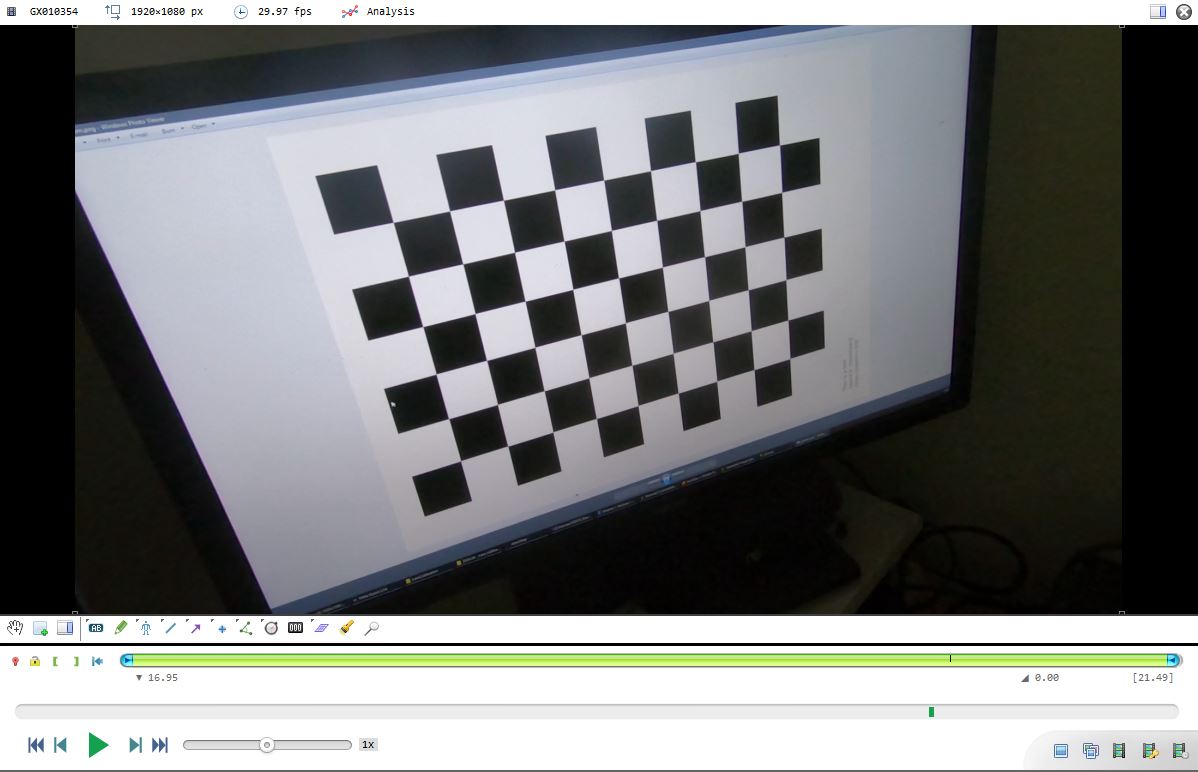
- When filming make sure the entire pattern is visible at all time, about a quarter of the image size
- Don't move too fast to avoid motion blur
- You don't have to print the image, just display it on a flat screen or a tablet
- The physical size of the filmed pattern doesn't matter
- You can either move the camera or move the checkerboard pattern, it doesn't matter
- You can use a different checker board pattern as long as you adjust the parameters in the configuration
Open the lens calibration mode
Load the video of the calibration pattern in Kinovea.
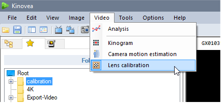
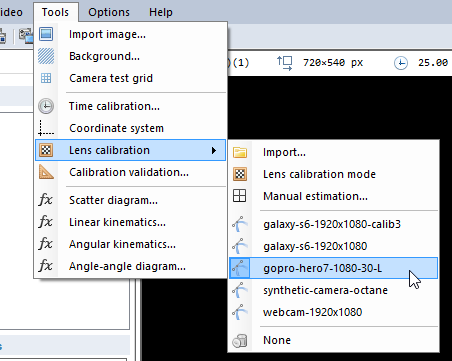
Open the lens calibration mode using the menu Video > Lens calibration. This mode is also available from the menu Tools > Lens calibration > Lens calibration mode.
Note: this will only be available when the video is short enough to trigger the “cached” mode (or
enough cache memory is allocated).
Run lens calibration
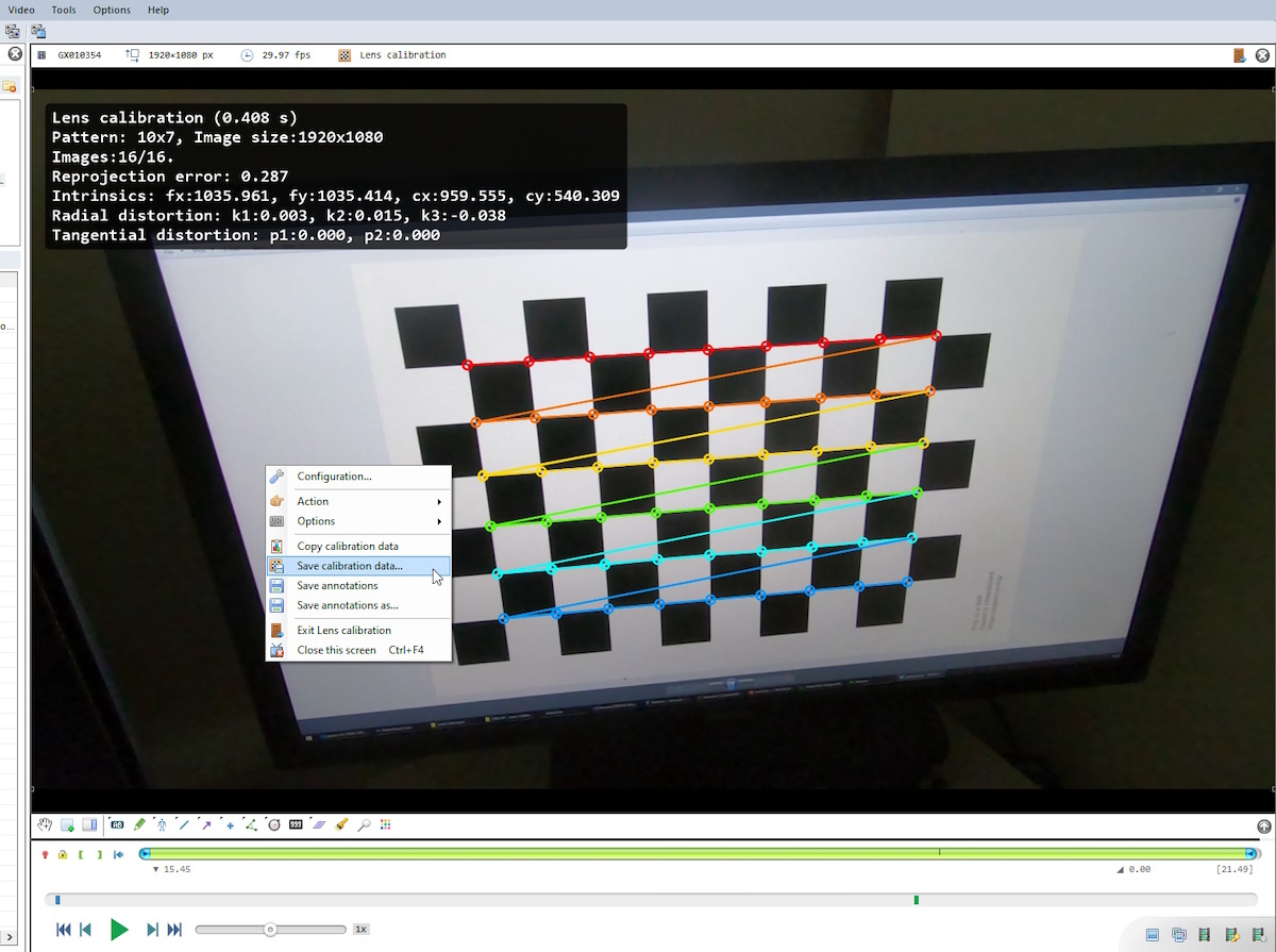
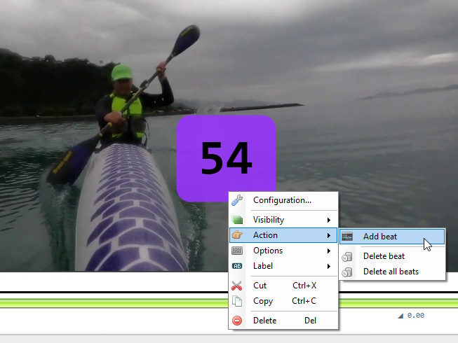
Right click the background and select menu Action > Run lens calibration.
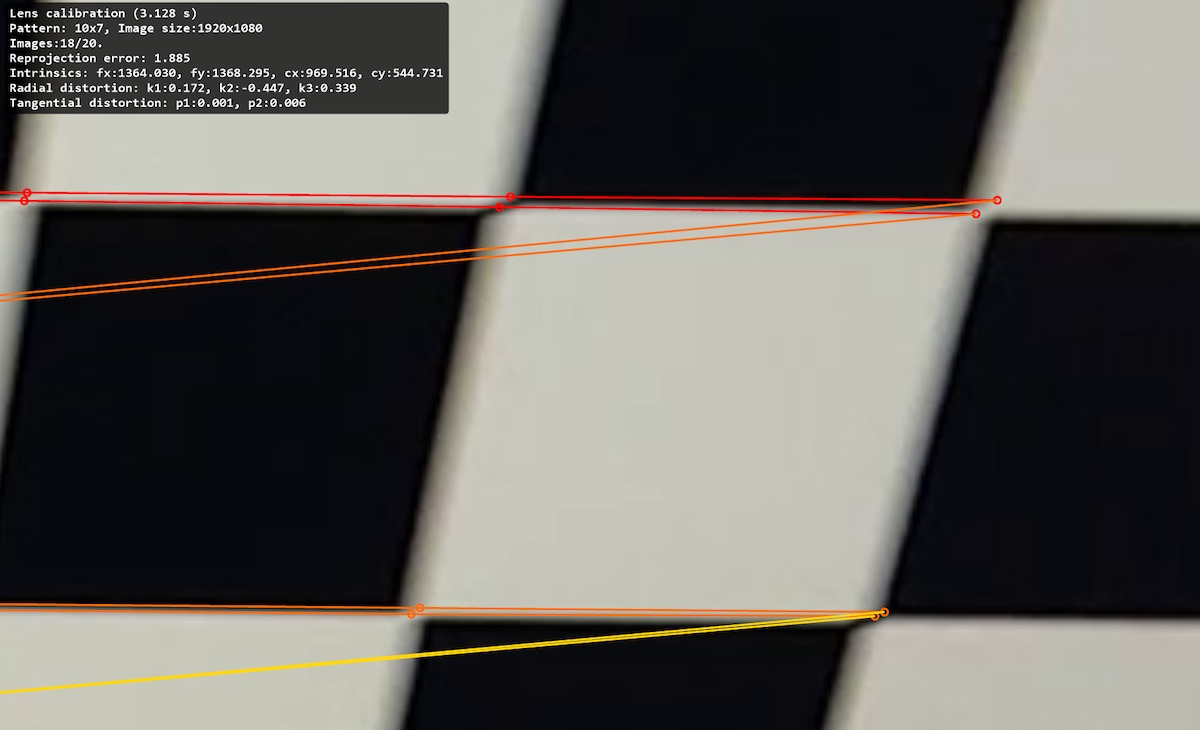
It will show a progress bar while it calculates the parameters. When the calculation is complete it will paint the corners it has found on the checker board and display the results in the top left corner.
In this mode the player only shows the few frames used to perform the computation. Navigate the video and inspect the result. The colored patterns shows the detected corners and the reprojected corners based on the calculated calibration. There should not be any large divergence between the two.
Here is an example of a bad result due to poor lighting and motion blur on several frames
Lens calibration configuration
The algorithm can be configured by right clicking in the background of the video and selecting the menu Configuration…
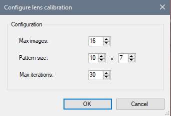
- Max images: number of images used for the computation
- Pattern size: the number of columns and rows of the checker board pattern to detect in the images. This must match the images
- Max iterations: number of iterations used by the optimization loop.
Save the data
Once you are happy with the result save the calibration data to a file by using the Save calibration data… menu.
Give it a descriptive name and save it preferably under the CameraCalibration folder in the Application Data folder of Kinovea to make it directly available as a menu in the program.
Load an existing calibration
If you have saved the calibration file in the Application data under the CameraCalibration folder, it will appear in the Tools > Lens calibration menu. Pick the calibration corresponding to the camera used to film the current video to load the data.
If you saved the lens calibration file elsewhere you may load it manually using the Import menu.
! Note
Any change of camera model, lens, or configuration options involving image resolution or zoom requires a new calibration procedure.