1

hi Joan,

in line with the hurdle analysis in the other thread, I would like to suggest a new feature. Would it be possible to set the zero point of the calibration grid to an arbitrary value so that all points are moved.
We measure the positions and step lengths during hurdles with two cameras. One records the start and the first 10m, the other camera from 5m to 15m. We would like to set the zero point of the calibration grid at 10m after the start line so that the positions of the steps measured form the second camera always refer to the start line.

https://i.postimg.cc/4yL0xpDy/Origin.jpg

Would it be possible?

Many greetings, Christian

2

So the way to do that right now is to activate the display of the coordinate system, then you can drag the axes to move the origin to the point you want. It saves this origin separately from the calibration. You can't set it numerically at the moment, maybe this would be good to have.

3

Another feature I'm just getting to know :-)
I studied your code over the weekend and have a possible implementation. The following function is inserted into CalibrationHelper

public void SetOriginFromWorld(PointF p)
{
      calibrator.SetOriginFromWorld(p);
      AfterCalibrationChanged();
}

in CalibrationPlane insert the function

public void SetOriginFromWorld(PointF p)
{
    if (!initialized)
        return;

    origin = new PointF {X = -p.X, Y=p.Y };
}

and in FormCalibrationPlane insert the line at the end of the try block of the btnOK_Click() function:

calibrationHelper.SetOriginFromWorld(new PointF() { X= tbX.Text, Y= a+tbY.Text });

Then the origin can be inserted from two new text boxes tbX and tbY, in which the origin can then be specified in the form x = 5000 (cm) and y = 20 (cm) and the origin of the perspective grid is then at [5000;20].

Should I send a pull request?

4

OK but it needs to interact nicely with changing the origin manually from dragging the Coordinate system object around by the axes or the origin. If we change manually on screen and we come back in this dialog it needs to show a correct value.

And we can also activate tracking on the coordinate system. In this case the value we would show here would be a bit tricky, maybe in this case it should be grayed out.

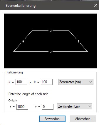
There are two ways to think about this I think. Option 1: this defines where the origin of the coordinate system is in relation to the calibration grid, this is what you wrote. When we activate the display of the coordinate system it will be moved to this new origin. If the origin is far enough it could be outside the image.

Option 2: it could define the coordinate at the origin, that is, a fixed offset applied to the coordinate system such that the intersection of the axes is not {0, 0} but something else.

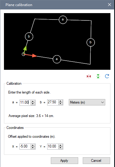
This is sort of what I do in the new "Distance grid" object (on horizontal axis only though, but it could be done on two axes). In the calibration of this grid you set two distances, for example 6m and 10m, and then even a coordinate on the main axis is already at 6m. This was designed as an experiment for long jump measurements. The important advantage of doing it this way is when the true origin of your coordinate system is way outside the image. So we have a camera looking at the end of the long jump pit with markers at known distance. The coordinate system is still aligned with the grid but the values are pre-transformed. (edit: it doesn't really work fully with the coordinate system at the moment though, only for the distance line inside the grid).

Can you tell if your use case is more amenable to one way or the other? I wonder if people that want to change the origin numerically are actually looking for option 2.

5

Wow, Kinovea is like excel: every day you get to know a new feature :-)

What is a use case for the tracking of a perspective grid?

You are right, if the grid is moved manually, the new value of the origin must be displayed in the calibration form. To do this, it would have to be entered when loading the calibration form.

For my application, option 2 is enough for me. I have a fixed camera and would like to move the grid relative to the origin, whereby the origin is no longer in the image. If that goes across both axes, that would be great. Then all you have to do is adjust the measured values of the crossmarks accordingly. It would probably also make sense to deactivate tracking on this grid, as it makes handling clearer and programming easier. It will then only work with a fixed camera, which will be the main application, in my opinion.

I would like to have an option to show both grid lines, because this helps to align the grid to the track and the lanes. Then the distance grid would be a perspective grid with a numerical origin and no tracking.

6

To be clear, you can track the grid, but you can also track the coordinate system origin, independently. If you first move the coordinate system out of the grid corner, then you can right click > Tracking > Start tracking. If both the coordinate system origin and the calibration grid are tracked, then the priority is given to the grid.

To be honest I think the only real use-case of tracking the calibration grid itself is when the camera is moving. I've been working on camera motion compensation for a while and it should be in the next version, although I'm not yet sure if the first version will interact correctly with measurements (it's working for placing drawings that "stick" on world objects despite camera motion, this is already useful for visualizing trajectories and drawing in world space).

Tracking the system's origin has a use case outside camera motion, it's for example when you want to measure something relatively to something else (moving coordinate system). It's not very common in my experience though.

Yeah I think having a configurable "offset" to the coordinate system would be nice. The two options aren't mutually exclusive. This might be useful in the context of camera tracking actually. To set up your calibration in the middle of the sequence but still get meaningful values. Although I'm not sure if camera tracking will be precise enough for making measurements.

7 (edited by Chris_G 2023-09-29 14:32:05)

I played with the tracking again to find possible scenarios. I haven't used the function yet. Now I understand the problem with the offset to the origin when the grid and the origin are tracked.

Would it be possible to programmatically deactivate tracking at the perspective grid or at the origin? Then a checkbox could be displayed in the calibration form that allows the offset to be entered. Two radio buttons are also displayed with which you can choose whether tracking of the grid or the origin is deactivated.
This makes it clear to the user that only one of the two can be tracked when the offset is activated. It would have to be checked beforehand whether tracking has already started on both. Then the checkbox can be deactivated and the offset is not possible.
When tracking of the grid has started, the radio button for the origin will be grayed out and vice versa. If no tracking takes place or will take place, it doesn't matter which radio button is selected.

This would be the most flexible solution and would work with fixed cameras and panned video recordings. However, it is also very complex to program...

Edit: Camera motion compensation sounds very interesting and I'm excited about the feature. Have you seen this project https://encord.com/blog/cotracker-metai/ for tracking objects? It's brand new and looks very exciting. I haven't managed to test yet.

8

Another way is to have a second way of entering the calibration grid dimensions, instead of entering the sizes of the sides, to enter the coordinates of the bottom-left and the top-right corners. If the user chooses this way we calculate the sides and the offset from the entered values. (In theory this could be an aribitrary quad but it makes things simpler to force a rectangle).

That was kind of the direction the Distance grid tool experiment was going. But now I think this tool won't be necessary anymore, if the offset can be set up on the normal grid. Then the distance line can become a display option (and it can have a vertical distance as well).

The link to meta ai tracking project is super interesting. When the basic camera motion integration is done I want to look into connecting machine learning algorithms more easily. There is so much to leverage, super-slow-motion, pose estimation, background/foreground segmentation, image stabilization…

9 (edited by joan 2023-09-30 22:58:01)

Another feature of the Distance grid tool is that it lets you reverse the X axis direction and anchor the origin at the bottom-right. This can be useful for measuring things going right-to-left. I'll try to get all of this in the normal grid.

edit: actually this can be done by manually flipping the grid.

10

Updated calibration dialog.

https://www.kinovea.org/screencaps/2023.2/2023.2-calibration.png

- New: flipping and rotating axes, pixel size hint, coordinates offset.
- Improved: using numeric box instead of text box to support mouse scroll to change the numbers.
- Plus: added a menu in the coordinate system drawing to re-align it with the grid.

Pixel size can be thought of as the error bar at the center of the grid. If the digitization is off by one pixel this is how much it is off in real world units. (in pixels of the original video, not screen pixels, always good to zoom in).

No special treatment for tracking. The offset is just added at the end so it should work as before. I don't think tracking both the coordinate system and the calibration grid is a realistic scenario so until someone comes with a real use-case it will just keep giving precedence to the grid. We'll see later how that works with camera motion compensation.

Known limitation: The scatter plot diagram is showing the axes un-flipped.

11

Perfect. The new interface looks great and works very well. I tested the new functions and didn't find any bugs. I think we will do some hurdle analysis soon and see if any errors occur.

It's great to get the transformed data in json and not have to transform it manually. This is good because there have also been changes in the kva format, for example, the world coordinates of the crossmarks are no longer written to the kva file.

Thank you for the quick implementation!