1 (edited by arnopluk 2018-02-08 12:30:59)

Hello Joan,

I'm playing around with the custom tools, a very nice feature of Kinovea! I'm using Kinovea 0.8.26 64bit.
Unfortunately, I couldn't find that much documentation about the xml format of the files. So far, I've run into a couple of things I can't get a grip on right now:

  • Is it possible to specify the position of labels for angles (like 'radius')?

  • With 'optionGroup' you can specify options which can be selected by the user. Can you specify the default options which are used? (In Human Model 2 I found the keyword 'DefaultOptions', but no example how to use it.)

  • I would like to have 2 constraints in effect for my handle: 1. Fixed length ('DistanceToPoint') and 2. Rotation in steps of 5 degrees ('RotationSteps'). However, only the constraint that is configured last, is used by Kinovea.

  • Is it possible to lock handles so they can't be changed by the user?
    For example: Lock the angle-to-vertical of a certain line, while allowing a user to change its length.

  • Can the position of annotation in the capture screen be saved?
    For example: Default annotation in a fixed-camera setup.

  • (edit) How can I make my own icons for the custom tools?

Regards,
Arno

2

Cool! I also think it's one of the most powerful feature in the program, but yeah the documentation is certainly lacking.
I will get around to at least write a page with a raw list of each node and the attributes they support.

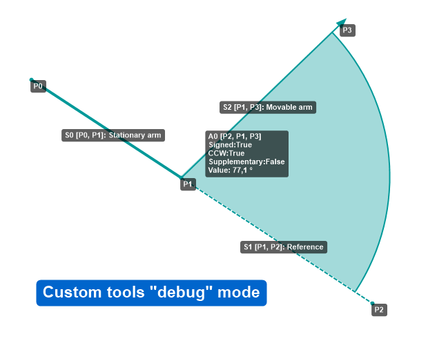
If you haven't seen it already, here is an article discussing custom tools: http://www.kinovea.org/en/creating-a-custom-tool/

arnopluk wrote:

Is it possible to specify the position of labels for angles (like 'radius')?

No, at the moment the text distance is hardcoded. It's a good point though, I'll add that to the backlog for the next version.

arnopluk wrote:

With 'optionGroup' you can specify options which can be selected by the user. Can you specify the default options which are used? (In Human Model 2 I found the keyword 'DefaultOptions', but no example how to use it.)

Yes. I'll recap how this works for everyone and then add more details on declaring default options.

Each object visibility (objects: segment, handle, ellipse, angle, distance, position, computed point) can be controlled by named "options". These options end up in the context menu of the drawing and can be toggled on/off by the user. Options can also control the enabling of "constraints" placed on handles, such that the handle can be freely moved or constrained based on user desire.

This is controlled by specifying optionGroup="name of option" as an attribute on the object. Multiple objects' visibility or constraints in different objects can be controlled by the same option. There can be multiple options in the drawing.

Option discovery is entirely based on the textual name so be sure to correctly copy & paste the name otherwise they will end up as two different options.

By default all options are "off". To specify default options that are "on", create a "DefaultOptions" node and add the named options under "OptionGroup" subnodes, as following:

<DefaultOptions>
    <OptionGroup>Display ankle angles</OptionGroup>
    <OptionGroup>Display hips angles</OptionGroup>
</DefaultOptions>

Options listed here that are not matched to an option declared elsewhere will be ignored.

arnopluk wrote:

I would like to have 2 constraints in effect for my handle: 1. Fixed length ('DistanceToPoint') and 2. Rotation in steps of 5 degrees ('RotationSteps'). However, only the constraint that is configured last, is used by Kinovea.

Yes you are right. I didn't anticipate that use-case, all the other constraints are mutually exclusive I think, but rotation steps could be combined with others. This is not possible at the moment.

arnopluk wrote:

Is it possible to lock handles so they can't be changed by the user?
For example: Lock the angle-to-vertical of a certain line, while allowing a user to change its length.

For that specific scenario I think you could use a "LineSlide" constraint, where a handle is only allowed to move along a line defined by two other points. The LineSlide constraint takes "point1", "point2" and "position" attribute. The "position" attribute further determines where the handle can go in relation to the two existing points, and can take the following values: BeforeSegment, BeforeAndOnSegment, OnSegment, AfterAndOnSegment, AfterSegment, Anywhere.  Check the "Archery top view" tool for an example.

So you would first make sure your have two points defining the fixed-angle line in the point list  (without necessary creating a visible segment from them). Then add a third point and a handle referencing it, with a constraint that only allows it to slide along the line defined by the other two, maybe using AfterAndOnSegment. Then you can create a segment object that goes from the angle origin to the sliding point.

I just realized that creating a completely locked point is harder than necessary. You can create a "Point" but it won't be visible until it's either a handle or a computed point. Right now the only way seems to be to create two dummy points and create computed point based on them. Or maybe a collapsed segment. I should probably add a simpler constraint that completely locks a handle in place.

How can I make my own icons for the custom tools?

The gist of it is that the "Icon" node contains the Base64 encoded image. In practice:

Can the position of annotation in the capture screen be saved?
For example: Default annotation in a fixed-camera setup.

You can have a KVA file that is always loaded when you open a camera.

Create the annotations in the playback screen (maybe by reloading a video captured from the camera for alignment) and save them to a KVA file named "capture.kva" (File > Save > Save only the analysis). Then place that file in Kinovea %appdata% directory. The location of this directory depends on whether you are running the installed or zipped version, but you can get to it from menu Help > Open log folder.

The same can be done for the playback screen using "playback.kva". It's an application-wide thing though, there is currently no support for per-camera default KVA.

3

Hi,

I have addressed the following points for the next release:

1. Position of the text for angles

There is now a "textDistance" attribute on the angle node.

<Angle origin="1" leg1="2" leg2="3" signed="true" ccw="true" supplementary="false" radius="0" textDistance="40" tenth="true"/>

2. Double constraint fixed length + rotation steps.

The rotation steps constraint now has an attribute "keepDistance" that will force the point to stay at the same distance from the origin. I think it still didn't make sense to have a full multi-constraints system, as this was the only meaningful combination of two constraints.

<Constraint type="RotationSteps">
        <RotationSteps origin="1" leg1="0" step="5" keepDistance="true" />
</Constraint>

Note that the existing "DistanceToPoint" constraint supports the SHIFT modifier that forces segments to lock onto 45° steps. This is supported out of the box and doesn't need any specifics in the tool file.

3. Completely locked points.

There is now a "LockedInPlace" constraint that will simply ignore the applied motion.

<Constraint type="LockedInPlace" />

In addition to that, there is now a debug mode for the custom tools. It will be available from menu Options > Preferences > Drawings > General, check box "Custom tools debug mode". It will show the points ids, the segments ids and names, and angles ids and parameters. Counting starts at 0.

http://www.kinovea.org/screencaps/0.8.27/customtooldebug3.png

4

Hi Joan,
Thanks again for the updates:

It seems that the documentation for the custom tools has been moved? The link you provided above (http://www.kinovea.org/en/creating-a-custom-tool/) is dead now.

In the newest version (0.9.1) some changes have been made to the custom tooling.
Two changes I have seen so far:

1. New way of creating points (old way still works):

<Points>
    <Point name="Origin centre" value="200;200" color="#FFFF00" />
</Points>

2. The example and explanation above about the '<DefaultOptions>' don't work any more in 0.9.1.
Options can now be declared separately and given a 'default' status in the following way:

<Options>
    <Option key="15deg" label="15 degrees"  default="true"  hidden="false" />
    <Option key="30deg" label="30 degrees"  default="false"  hidden="false" />
    <Option key="showLabel" label="Show labels"  default="false"  hidden="false" />
</Options>

Options can also be combined now (don't know if that was already the case):

optionGroup="showLabel|15deg" <!-- Shows if showLabel option AND 15deg option are both selected -->
optionGroup="showLabel|30deg" <!-- Shows if showLabel option AND 30deg option are both selected -->

One question I have left:

1. Position of the text for angles

There is now a "textDistance" attribute on the angle node.

<Angle origin="1" leg1="2" leg2="3" signed="true" ccw="true" supplementary="false" radius="0" textDistance="40" tenth="true"/>

What is the unit of 'textDistance' and 'radius'? If I have segments of 200 pixels long and radius and textDistance set to 200; the radius and text are displayed at +/-55% of the line segments.

5

Yes you are right, the format was updated, although the old format should still work for the most part.
It was indeed not possible for an object to be controlled by multiple options.

For documentation, the old page was painful to maintain. What I would like to do instead is have a "sample" tool with a collection of everything possible and many comments in the XML. This tool would be available in the menu as any other so you could experiment with it directly to find the appropriate object and mechanism, and then copy-paste the relevant parts.

For text distance, it is the distance to the center of the label, in pixels. The rectangular area covered by the text is first measured, based on the text itself and font size, and then the center of that rectangle is placed at the textDistance value, along the bisector of the angle.

6

Below an example of part of my tool. The points in this image are 200 pixels from origin, the textdistance and radius is also set to 200.
https://www.dropbox.com/s/z66fl6uo7effx … e.png?dl=0

7

It could be related to how the points coordinates are rescaled when the object is loaded into a video, to match the target image size.

Edit: there are several issues, this will need further investigation. First the textDistance wasn't properly scaled when adding the tool the first time. Secondly, the scaled values for the angles weren't taken into account anyway. These don't exactly match your symptom though. Then there is an issue that when saving the tool in KVA, it only saves the points and it looses the scaling information.

8

I committed a fix, it should respect the original proportion of the tool now.

Note that the scaling reference is hard coded at the moment. There is a virtual 800x600 canvas that the custom tool is assumed to be drawn on to, and when adding the tool it will be upscaled or down-scaled depending on the size of the target video. So for example if the initial point list covers half of this virtual canvas, they will also cover half of the image when the tool is added. This should probably be something controlled directly within the tool XML.

9

Thanks for the quick reply and fix!