Opening a dedicated thread on this camera as it seems fairly popular due to its price and announced specs.
It is based on the Omnivision sensor OV4689, and is advertised as 1920x1080 @ 60 fps, 1280x720 @ 120 fps and 640x360 @ 330 fps, rolling shutter, for around 100€ depending on where you source it from.
It is variously known as KYT-U400-***, RYS HFR USB2.0 Camera, Webcam UVC High Fram Rate USB Camera, Kayeton 330 fps, etc. It is made by Kayeton (Shenzhen). USB vendor ID is VID=15aa, product ID is PID=1555. (Although I would be surprised if this was a legit Id from USB-IF).
I received a unit a few days ago and so far I'm not impressed…
Issues I have on my camera:
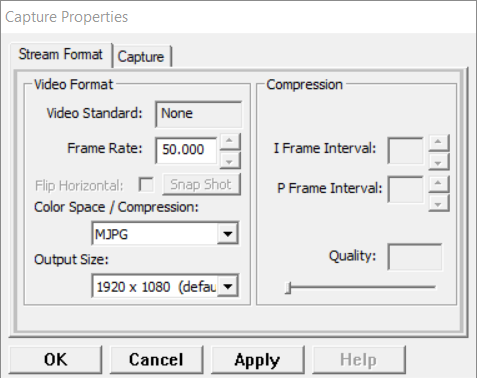
- It cannot be configured to 1920x1080 @ 60 fps but 50 fps.
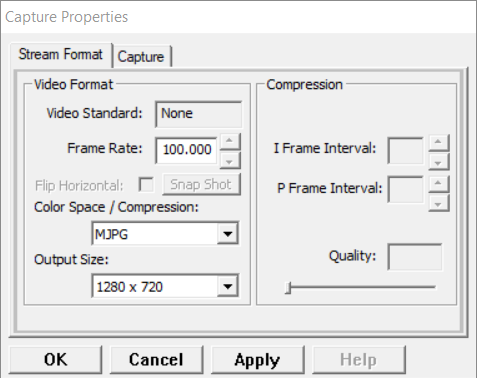
- It cannot be configured to 1280x720 @ 120 fps but 100 fps.
- When configured on 1920x1080 @ 50 fps, it is sending frames at ~49 fps.
- When configured on 1280x720 @ 100 fps, it is sending frames at ~99 fps.
- When configured on 640x360 @ 330 fps, it is sending frames at ~322 fps.
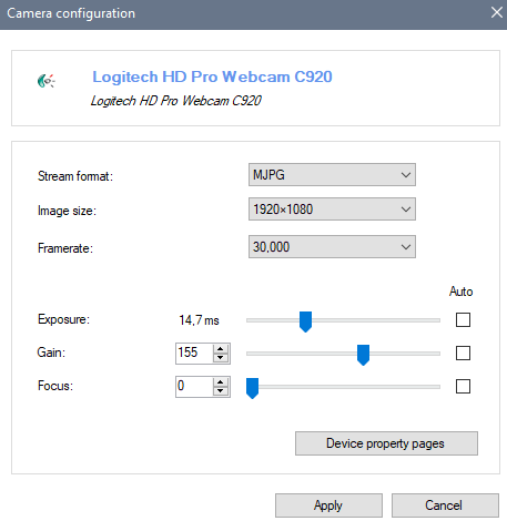
- Auto exposure can be toggled off, but changing exposure value manually doesn't have any effect.
I'm wondering if I just lost the Shenzhen roulette or if there is a different driver somewhere, or if all shipped units are actually like this. The sales rep on Alibaba is unresponsive.
If you have this camera please report whether you can configure it according to the vendor claims, in any software, thanks.
Note that Kayeton also has a "Global shutter" 1280x720 @ 120 fps camera, a different model, based on an unnammed OV sensor and doing only one resolution/framerate. If you have this one instead please state so.
Thanks